
Some Basic electronics projects
RECTIFYING a Voltage
These circuits show how to change an oscillating voltage (commonly called AC) to DC. The term AC means Alternating Current but it really means Alternating Voltage as the rising and falling voltage produces an increasing and decreasing current.
The term DC means Direct Current but it actually means Direct or unchanging Voltage.
The output of the following circuits will not be pure DC (like that from a battery) but will contain ripple. Ripple is reduced by adding a capacitor (electrolytic) to the output.
The term DC means Direct Current but it actually means Direct or unchanging Voltage.
The output of the following circuits will not be pure DC (like that from a battery) but will contain ripple. Ripple is reduced by adding a capacitor (electrolytic) to the output.
DARK DETECTOR with beep-beep-beep Alarm
This circuit detects darkness and produces a beep-beep-beep alarm. The first two transistors form a high-gain amplifier with feedback via the 4u7 to produce a low-frequency oscillator. This provides voltage for the second oscillator (across the 1k resistor) to drive a speaker.
3-PHASE SINEWAVE GENERATOR
This circuit produces a sinewave and each phase can be tapped at the point shown.
TRANSFORMERLESS POWER SUPPLY

This clever design uses 4 diodes in a bridge to produce a fixed voltage power supply capable of supplying 35mA.
All diodes (every type of diode) are zener diodes. They all break down at a particular voltage. The fact is, a power diode breaks down at 100v or 400v and its zener characteristic is not useful.
But if we put 2 zener diodes in a bridge with two ordinary power diodes, the bridge will break-down at the voltage of the zener. This is what we have done. If we use 18v zeners, the output will be 17v4.
When the incoming voltage is positive at the top, the left zener provides 18v limit (and the left power-diode produces a drop of 0.6v). This allows the right zener to pass current just like a normal diode but the voltage available to it is just 18v. The output of the right zener is 17v4. The same with the other half-cycle.
The current is limited by the value of the X2 capacitor and this is 7mA for each 100n when in full-wave (as per this circuit). We have 10 x 100n = 1u capacitance. Theoretically the circuit will supply 70mA but we found it will only deliver 35mA before the output drops. The capacitor should comply with X1 or X2 class. The 10R is a safety-fuse resistor.
The problem with this power supply is the "live" nature of the negative rail. When the power supply is connected as shown, the negative rail is 0.7v above neutral. If the mains is reversed, the negative rail is 340v (peak) above neutral and this will kill you as the current will flow through the diode and be lethal. You need to touch the negative rail (or the positive rail) and any earthed device such as a toaster to get killed. The only solution is the project being powered must be totally enclosed in a box with no outputs.
LEDs on 240v
I do not like any circuit connected directly to 240v mains. However Christmas tress lights have been connected directly to the mains for 30 years without any major problems.
Insulation must be provided and the lights (LEDs) must be away from prying fingers.
Read the article above for the type of capacitor and add an equal number of LEDs in each string so the reverse voltage is equal across each LED.
It does not matter how many LEDs you add to each string as the brightness will be the same. As you add each pair, the current will drop a very small amount until eventually, when you have 100 LEDs in each string, the current will be zero.
For the circuit shown, each LED will see 20mA peak during the half-cycle they are illuminated. The 1k resistor will drop 15v - since the RMS current is 15mA (15mA x 1,000 ohms = 15v). No rectifier diodes are needed. The LEDs are the "rectifiers." Very clever. You must have LEDs in both directions to charge and discharge the capacitor. The resistor is provided to take a heavy surge current through one of the strings of LEDs if the circuit is switched on when the mains is at a peak. A 100n cap will deliver 7mA RMS or 10mA peak in full wave or 3.5mA RMS (5mA peak) in half-wave. The LEDs above detect peak current.
Capacitor Supply
The current-capability of a capacitor needs more explanation. In the diagram on the left we see a capacitor feeding a full-wave power supply. This is exactly the same as the LEDs on 240v circuit above. Imagine the LOAD resistor is removed. Two of the diodes will face down and two will face up. This is exactly the same as the LEDs facing up and facing down in the circuit above. The only difference is the mid-point is joined. Since the voltage on the mid-point of one string is the same as the voltage at the mid-point of the other string, the link can be removed and the circuit will operate the same.
This means each 100n of capacitance will deliver 3.5mA RMS or 5mA peak on each half-cycle.
In the half-wave supply, the capacitor delivers 3.5mA RMS or 5mA peak for each 100n to the load and during the other half-cycle the 3.5mA RMS is lost in the diode that discharges the capacitor.
You can use any LEDs and try to keep the total voltage-drop in each string equal. Each string is actually working on DC, it's not constant DC but varying DC. In fact is it zero DC for 1/2 cycle then a gradual increase to full characteristic voltage-drop for each LED over a 1/4 cycle, then a gradual decrease to zero over another 1/4 cycle, then 0v for 1/2 cycle. Because the LEDs turn on and off, you may observe some flickering and that's why the two strings should be placed together.
BOOK LIGHT
This circuit keeps the globe illuminated for a few seconds after the switch is pressed.
There is one minor fault in the circuit. The 10k should be increased to 100k to increase the "ON" time.
The photo shows the circuit built with surface-mount components:
There is one minor fault in the circuit. The 10k should be increased to 100k to increase the "ON" time.
The photo shows the circuit built with surface-mount components:
CAMERA ACTIVATOR
This circuit was designed for a customer who wanted to trigger a camera after a short delay.
The output goes HIGH about 2 seconds after the switch is pressed. The LED turns on for about 0.25 seconds.
The circuit will accept either active HIGH or LOW input and the switch can remain pressed and it will not upset the operation of the circuit. The timing can be changed by adjusting the 1M trim pot and/or altering the value of the 470k.
MAKE YOUR OWN:
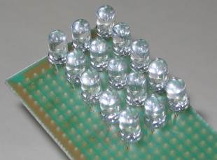
1-WATT LEDThis circuit drives 15 LEDs to produce the same brightness as a 1-watt LED. The circuit consumes 750mW but the LEDs are driven with high-frequency, high-voltage spikes, and become more-efficient and produce a brighter output that if driven by pure-DC.
The LEDs are connected in 3 strings of 5 LEDs. Each LED has a characteristic voltage of 3.2v to 3.6v making each chain between 16v and 18v. By selecting the LEDs we have produced 3 chains of 17.5v Five LEDs (in a string) has been done to allow the circuit to be powered by a 12v battery and allow the battery to be charged while the LEDs are illuminating. If only 4 LEDs are in series, the characteristic voltage may be as low as 12.8v and they may be over-driven when the battery is charging. (Even-up the characteristic voltage across each chain by checking the total voltage across them with an 19v supply and 470R dropper resistor.) The transformer is shown above. It is wound on a 10mH choke with the original winding removed. This circuit is called a "boost circuit." It is not designed to drive a single 1-watt LED (a buck circuit is needed).
The LEDs in the circuit are 20,000mcd with a viewing angle of 30 degrees (many of the LED specifications use "half angle." You have to test a LED to make sure of the angle). This equates to approximately 4 lumens per LED. The 4-watt CREE LED claims 160 lumens (or 40 lumens per watt). Our design is between 50 - 60 lumens per watt and it is a much-cheaper design.

1.5 WATT LED
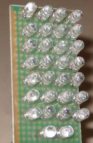
The circuit below can be modified to drive up to 30 white LEDs.
The effectiveness of a LED array increases when they are spread out slightly and this makes them more efficient than a single 1 watt or 2 watt LED.
The two modifications to the circuit make the BC337 work harder and this is the limit of the inductor. The current consumption is about 95mA.
The winding details for the transformer are shown above.

DRIVE 20 LEDs FROM 12v - approx 1watt circuit
This is another circuit that drives a number of LEDs or a single 1 watt LED. It is a "Buck Circuit" and drives the LEDs in parallel. They should be graded so that the characteristic voltage-drop across each of them is within 0.2v of all the other LEDs. The circuit will drive any number from 1 to 20 by changing the "sensor" resistor as shown on the circuit. The current consumption is about 95mA @ 12v and lower at 18v. The circuit can be put into dim mode by increasing the drive resistor to 2k2. The UF4004 is an ultra fast 1N4004 - similar to a high-speed diode. You can use 2 x 1N4148 signal diodes.
The circuit will not drive two LEDs in series - it runs out of voltage (and current) when the voltage across the load is 7v. It oscillates at approx 200kHz. Build both the 20 LED and 1 watt LED version and compare the brightness and effectiveness.
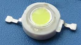
The photo of the 1 watt LED on the left must be heatsinked to prevent the LED overheating. The photo on the circuit diagram shows the LED mounted on a heatsink and the connecting wires.
The circuit will not drive two LEDs in series - it runs out of voltage (and current) when the voltage across the load is 7v. It oscillates at approx 200kHz. Build both the 20 LED and 1 watt LED version and compare the brightness and effectiveness.
The photo of the 1 watt LED on the left must be heatsinked to prevent the LED overheating. The photo on the circuit diagram shows the LED mounted on a heatsink and the connecting wires.
A 1-watt demo board showing the complex step-up circuitry.
This is a Boost circuit to illuminate the LED and is completely different to our design. It has been included to show the size of a 1 watt LED.
The reason for a Boost or Buck circuit to drive one or more LEDs is simple. The voltage across a LED is called a "characteristic voltage" and comes as a natural feature of the LED. We cannot alter it. To power the LED with exactly the correct amount of voltage (and current) you need a supply that is EXACTLY the same as the characteristic voltage. This is very difficult to do and so a resistor is normally added in series. But this resistor wastes a lot of energy. So, to keep the loses to a minimum, we pulse the LED with bursts of energy at a higher voltage and the LED absorbs them and produces light. With a Buck circuit, the transistor is turned on for a short period of time and illuminated the LEDs. At the same time, some of the energy is passed to the inductor so that the LEDs are not damaged. When the transistor is turned off, the energy from the inductor also gives a pulse of energy to the LEDs. When this has been delivered, the cycle starts again.
The reason for a Boost or Buck circuit to drive one or more LEDs is simple. The voltage across a LED is called a "characteristic voltage" and comes as a natural feature of the LED. We cannot alter it. To power the LED with exactly the correct amount of voltage (and current) you need a supply that is EXACTLY the same as the characteristic voltage. This is very difficult to do and so a resistor is normally added in series. But this resistor wastes a lot of energy. So, to keep the loses to a minimum, we pulse the LED with bursts of energy at a higher voltage and the LED absorbs them and produces light. With a Buck circuit, the transistor is turned on for a short period of time and illuminated the LEDs. At the same time, some of the energy is passed to the inductor so that the LEDs are not damaged. When the transistor is turned off, the energy from the inductor also gives a pulse of energy to the LEDs. When this has been delivered, the cycle starts again.
POWER SUPPLIES - FIXED:
A simple power supply can be made with a component called a "3-pin regulator or 3-terminal regulator" It will provide a very low ripple output (about 4mV to 10mV provided electrolytics are on the input and output.
The diagram above shows how to connect a regulator to create a power supply. The 7805 regulators can handle 100mA, 500mA and 1 amp, and produce an output of 5v, as shown.
These regulators are called linear regulators and drop about 4v across them - minimum. If the current flow is 1 amp, 4watts of heat must be dissipated via a large heatsink. If the output is 5v and input 12v, 7volts will be dropped across the regulator and 7watts must be dissipated.
POWER SUPPLIES - ADJUSTABLE
The LM317 regulators are adjustable and produce an output from 1.25 to about 35v. The LM317T regulator will deliver up to 1.5amp.
POWER SUPPLIES - ADJUSTABLE using 7805:
The 7805 range of regulators are called "fixed regulators" but they can be turned into adjustable regulators by "jacking-up" their output voltage. For a 5v regulator, the output can be 5v to 30v.
POWER SUPPLIES - ADJUSTABLE from 0v:
The LM317 regulator is adjustable from 1.25 to about 35v. To make the output 0v to 35v, two power diodes are placed as shown in the circuit. Approx 0.6v is dropped across each diode and this is where the 1.25v is "lost.
CONSTANT CURRENT
This constant current circuit can be adjusted to any value from a few milliamp to about 500mA - this is the limit of the BC337 transistor.
The circuit can also be called a current-limiting circuit and is ideal in a bench power supply to prevent the circuit you are testing from being damaged.
Approximately 4v is dropped across the regulator and 1.25v across the current-limiting section, so the input voltage (supply) has to be 5.25v above the required output voltage. Suppose you want to charge 4 Ni-Cad cells. Connect them to the output and adjust the 500R pot until the required charge-current is obtained.
The charger will now charge 1, 2, 3 or 4 cells at the same current. But you must remember to turn off the charger before the cells are fully charged as the circuit will not detect this and over-charge the cells.
The LM 317 3-terminal regulator will need to be heatsinked.
This circuit is designed for the LM series of regulator as they have a voltage differential of 1.25v between "adj" and "out" terminals.
7805 regulators can be used but the losses in the BC337 will be 4 times greater as the voltage across it will be 5v.
5v FROM OLD CELLS - circuit 1
This circuit takes the place of a 78L05 3-terminal regulator. It produces a constant 5v @ 100mA. You can use any old cells and get the last of their energy. Use an 8-cell holder. The voltage from 8 old cells will be about 10v and the circuit will operate down to about 7.5v. The regulation is very good at 10v, only dropping about 10mV for 100mA current flow (the 78L05 has 1mV drop). As the voltage drops, the output drops from 5v on no-load to 4.8v and 4.6v on 100mA current-flow. The pot can be adjusted to compensate for the voltage-drop. This type of circuit is called a LINEAR REGULATOR and is not very efficient (about 50% in this case). See circuit 2 below for BUCK REGULATOR circuit (about 85% efficient).
5v FROM OLD CELLS - circuit 2
This circuit is a BUCK REGULATOR. It can take the place of a 78L05 3-terminal regulator, but it is more efficient. It produces a constant 5v @ up to 200mA. You can use any old cells and get the last of their energy. Use an 8-cell holder. The voltage from 8 old cells will be about 10v and the circuit will operate down to about 7.5v. The regulation is very good at 10v, only dropping 10mV for up to 200mA output.
INCREASING THE OUTPUT CURRENT
The output current of all 3-terminal regulators can be increased by including a pass transistor. This transistor simply allows the current to flow through the collector-emitter leads.
The output voltage is maintained by the 3-terminal regulator but the current flows through the "pass transistor." This transistor is a power transistor and must be adequately heatsinked.
Normally a 2N3055 or TIP3055 is used for this application as it will handle up to 10 amps and creates a 10 amp power supply. The regulator can be 78L05 as all the current is delivered by the pass transistor.
SOFT START
The output voltage of a 3-terminal regulator can be designed to rise slowly. This has very limited application as many circuits do not like this.
LED DETECTS LIGHT

The LED in this circuit will detect light to turn on the oscillator. Ordinary red LEDs do not work. But green LEDs, yellow LEDs and high-bright white LEDs and high-bright red LEDs work very well.
The output voltage of the LED is up to 600mV when detecting very bright illumination.
When light is detected by the LED, its resistance decreases and a very small current flows into the base of the first transistor. The transistor amplifies this current about 200 times and the resistance between collector and emitter decreases. The 330k resistor on the collector is a current limiting resistor as the middle transistor only needs a very small current for the circuit to oscillate. If the current is too high, the circuit will "freeze."
The piezo diaphragm does not contain any active components and relies on the circuit to drive it to produce the tone. A different LED Detects Light circuit
